Reflecting on PLC Training at NAIT: Earning my credentials of PLC Ladder Logic Programming and PLC Advanced Programming.
TAGS: electronics; automation; industrial; PLC; Allen Bradley MicroLogix, CompactLogix, ControlLogix; Ladder; Function Block; Sequential Function Diagram; Structured Text
Why I Did This
One of the possible careers paths I wanted to branch into was Automation. I had previous
history with industrial operations,
so using industrial automation controls (dubbed Operational Technology) and using PLC
(programmable logic controllers) systems;
but less familiar with the programming side of it (I only 'heard' of Ladder logic and
function block programming).
NAIT offered courses in PLC programming, and I wanted to learn more about it. I took the PLC
Ladder Logic Programming and PLC Advanced Programming courses
where I learned to program in the different IEC 61131-3 languages (Ladder Logic, Function
Block Diagram, Structured Text, Sequential Function Chart,
but not Instruction List as lots of companies consider it too archaic). I also learned to
program Allen Bradley MicroLogix 1100 controllers using RSLogix 500 software; and then
CompactLogix 1769-L24ER controllers and 1756-L71 ControlLogix Logix5571
controllers using Studio 5000 Logix Designer.
We also did some short programming/training on a microsystems SCADAPack32 remote terminal
unit (RTU) when we were
learning of
different communications protocol/methods, but these were slower systems so the training was
minimally covered.
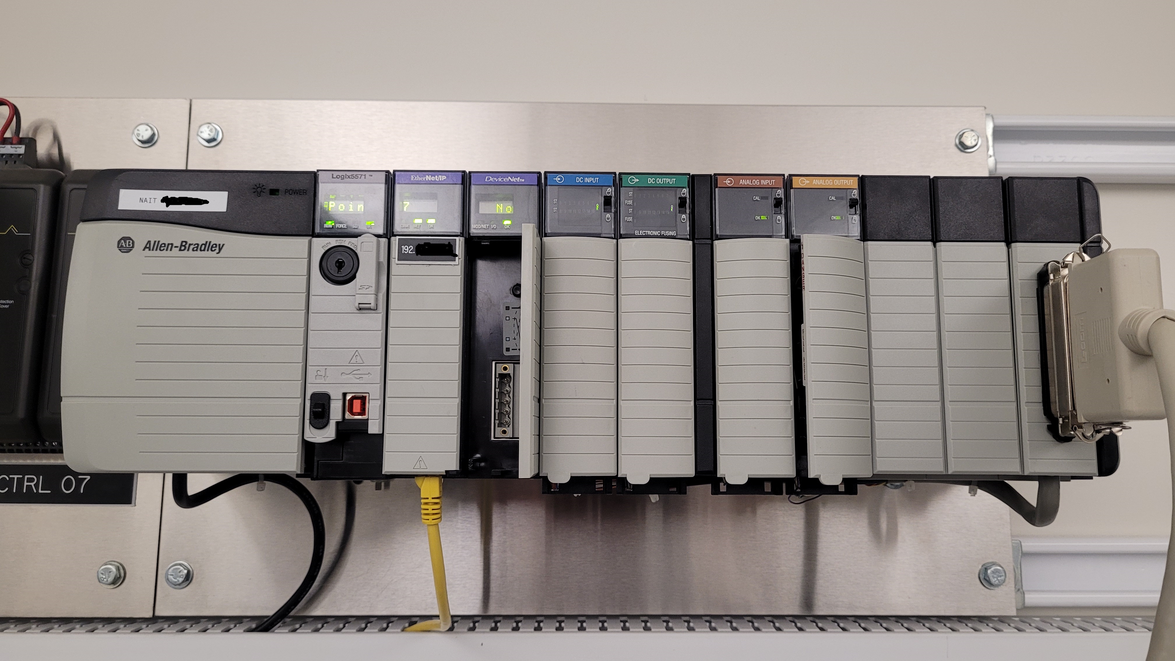
Our training was with using Allen Bradley's PLCs (MicroLogix, CompactLogix, ControlLogix); very popular industrial PLCs.
Course Highlights
- We learned about the general components of a PLC like the power unit, the CPU card,
communication cards (like Ethernet), and the various I/O cards like Digital Inputs, Digital
Outputs, Analog Inputs, and Analog Outputs.
- We learned to connect with PLCs using the RSLinx software, which allows our editor
(RSLogix 500 and Studio 5000) to connect via IP address to an available PLC set.
- We learned to connect with virtual plant software FactoryIO which can utlize our PLCs to
act as virtual plants with sensors and actuators, so we can virtually test our PLC
programming with realtime response.
- We developed in the Ladder logic language with extensive understanding of the scan cycle
(gather inputs, scan from top to botom rungs for states, set outputs)
and fundamental components (like tag making, contacts, coils, latches, comparators, timers,
counters, subroutines, etc.).
- We developed with more advanced components like the Oneshot, bitwise Move, and Forced bits
for troubleshooting, and online live editing/updating.
- We also delved into the status, error, and performance aspects where you can view the
fault/error codes and how to reset them, and the scan performance times.
- Advancing from the RSLogix 500 to Studio 5000 (much better and can do more than just
Ladder), we learned of fundamental PLC components in the Function Block Diagram, Seuqential
Function Chart, and Structured Text languages.
- Beyond virtual FactoryIO scenarios, we practiced with physical PLC trainer setups (with
physical buttons, switches, dials, LEDs, and value monitors).
- This extended to inter-PLC communications (and SCADA and communication understandings like
Modbus, Ethernet) with programs that incorporated messaging and Sender/Receiver tags.
- The communication teachings included using terminal 'pings' and free Wireshark software to
capture network communication.
- Overall, I learned immensely about PLC programming and the industrial automation field,
and I'm excited to see where I can apply this knowledge in the future.
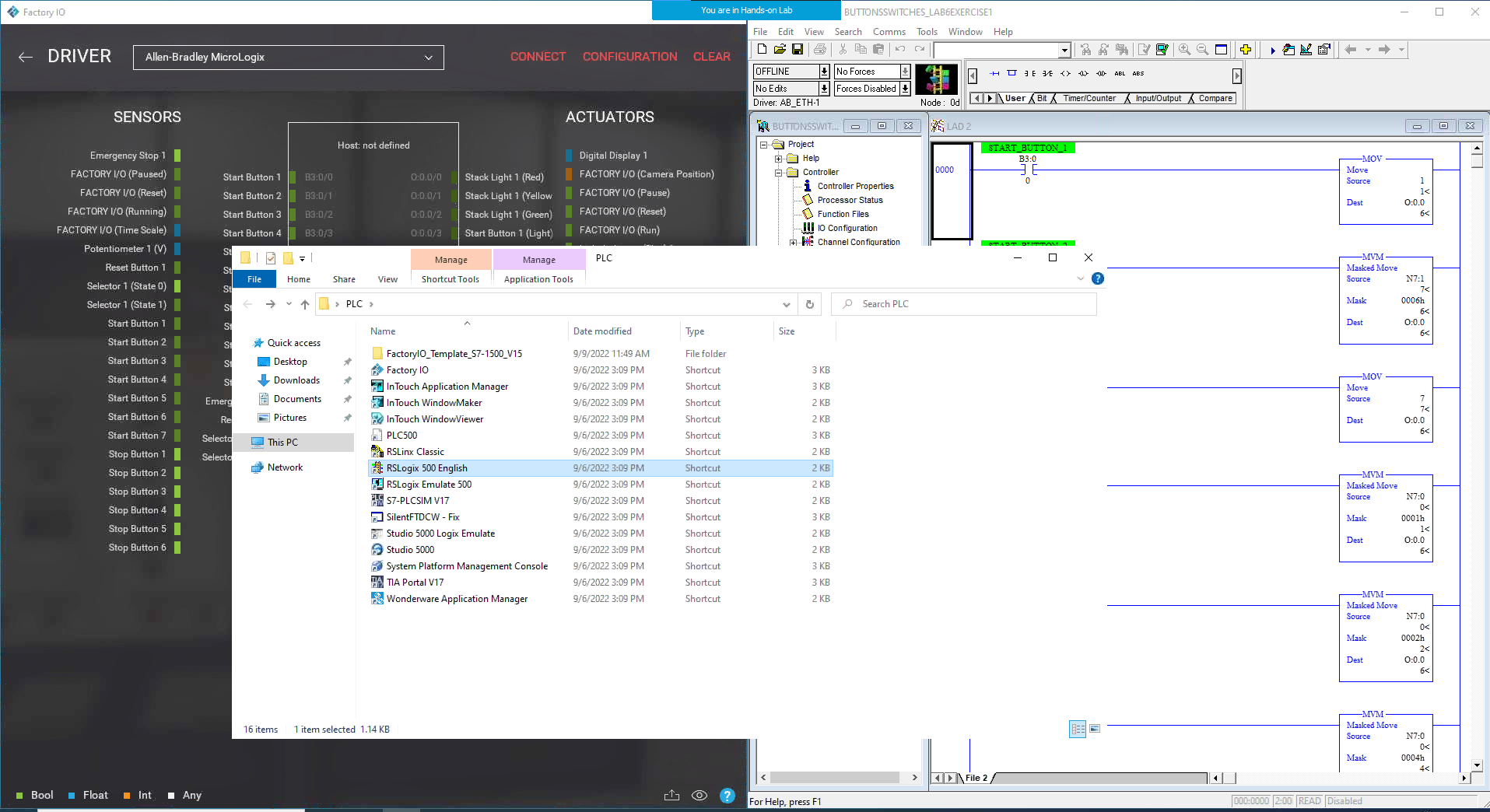
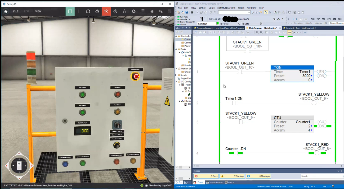
Our initial training was to remotely control some MicroLogix 1100 PLCs using RSLinx, which would then actuate virtual plant equipment hosted on FactoryIO (virtual plant software). We would use RSLogix 500 to made Ladder programs to control the PLCs and virtual scenes.
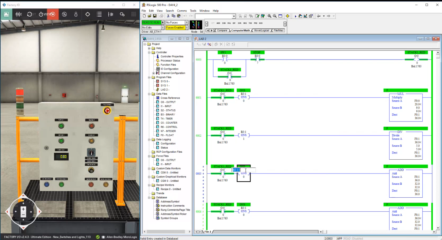
Here we experienced 'oneshot' controlling (ONS) that would do a calculation only once if the red light turned one. We also exeperience online live editing of programming (the 'e' and 'r' seen near the rung numbering) which allowed us to change the PLC program without shutdown and reuploading.
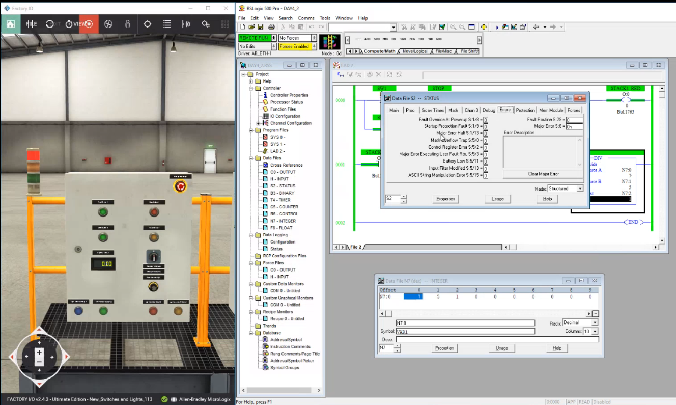
We also learned about monitoring and resetting fault/error detections, forcing bits (manual overriding of states; seen with the yellow box "Forces Enabled"), and checking PLC performance through scan cycle times (not shown, but you can see the "Scan Times" tab).
On later lessons we switched to Studio 5000 Logix Designer which was much more user friendly at programming compared to the 500 (aside from now being able to use languages other than Ladder).
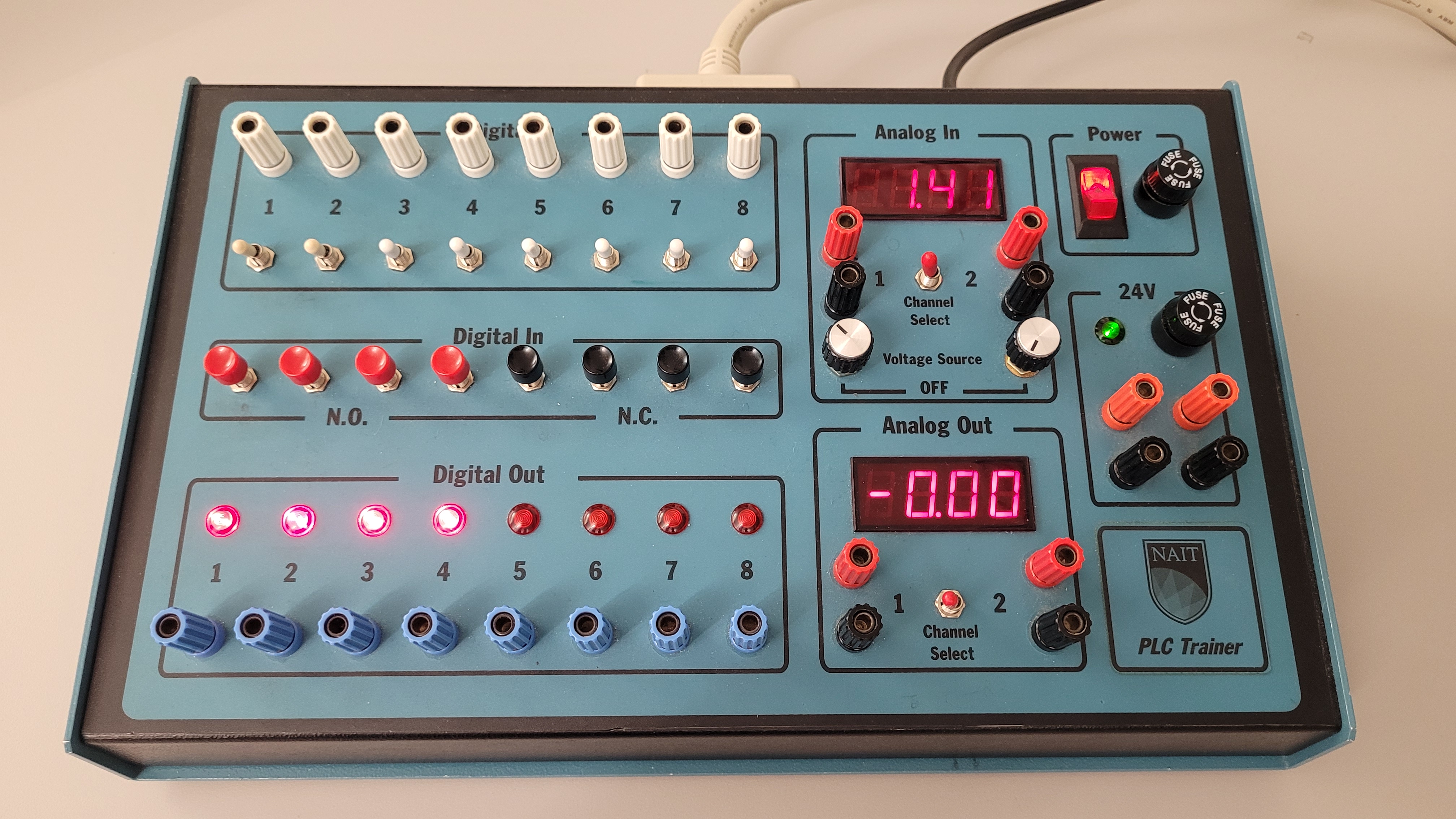
Aside from virtual FactoryIO sensors and actuators, NAIT also had physical PLC trainers for every workstation (with a variety of digital and analog, inputs and outputs).
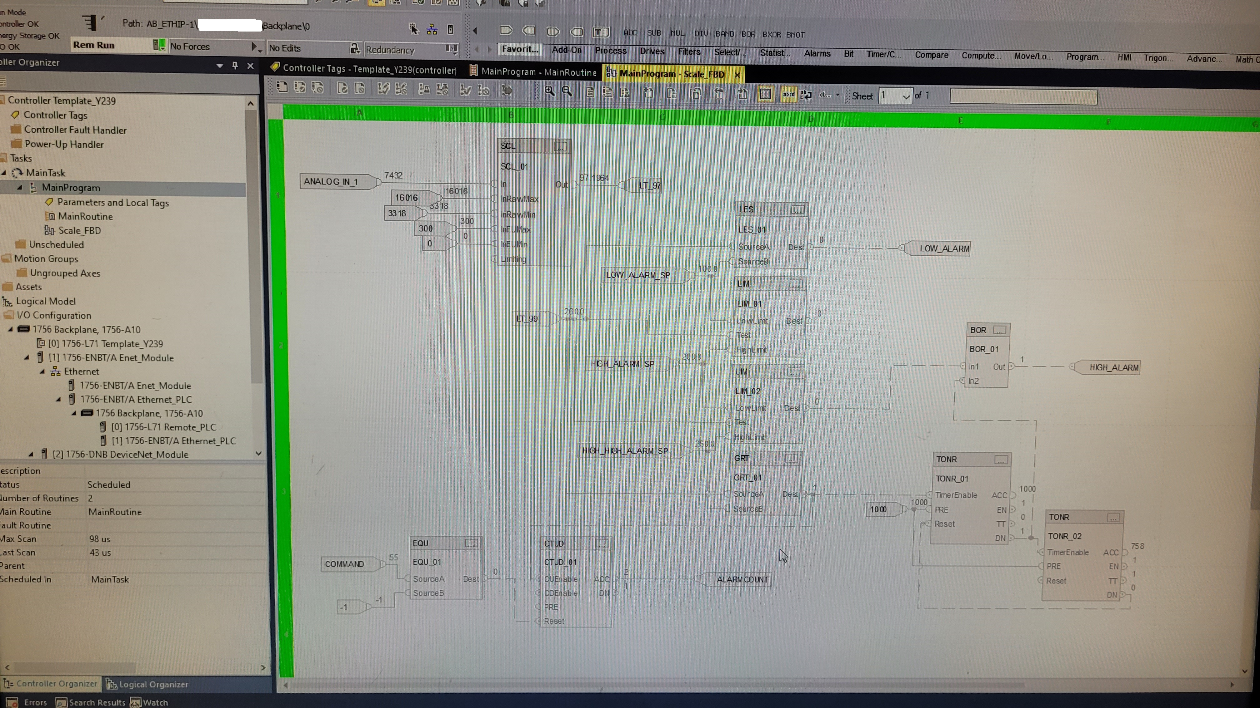
A Studio 5000 program written in the very popular Function Block Diagram language.
Using our station's PLC trainer, we could assign alarm states to the LED outputs
(plain-on and blinking states), and dial inputs to scaled values. In this
program, I take the analog dial input from my PLC trainer and scale it to a
value between 0 and 300, sending it to a LT_97 message variable/tag; I also
recieve a different LT_99 message tag from my teacher's PLC which feeds into
comparison blocks of less than (LES), limit-within (LIM), and greater-than
(GRT) along with setpoint variables to determine alarm states (low, high,
high-high). The low alarm turns on a specific light, while the high alarm turns
on another light, and the high-high alarm blinks the 'high' light (using two
Timer blocks).
Our teacher's PLC messages us the values of: the alarm setpoints, the LT_99
value, and
commands to reset a counter (utilized through an Equal block going to a reset
pin); while we send to our teacher messages of: our dial
0-300 output, our alarm states, and a count of the alarms (using a Counter
block).
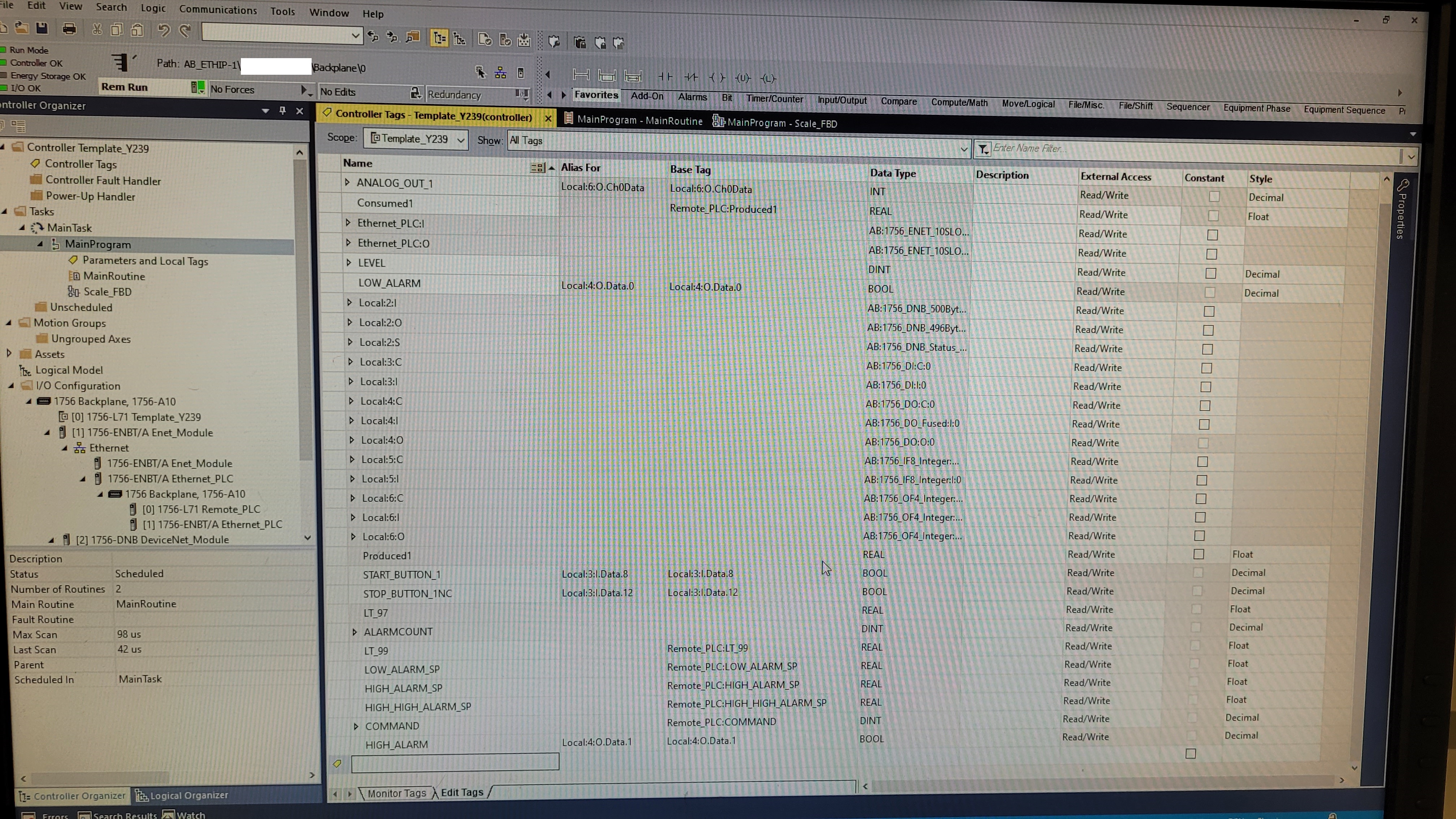
We were shown how to setup Ethernet links to other PLCs in our local network (through IP addresses and Ethernet/IP protocol), and then assigning variables/tags messages corresponding to those other PLCs. We learned of the passive messaging style of producer and consumer tags (seen in the above 2 photos), but also of explicit messaging though messaging functions blocks.
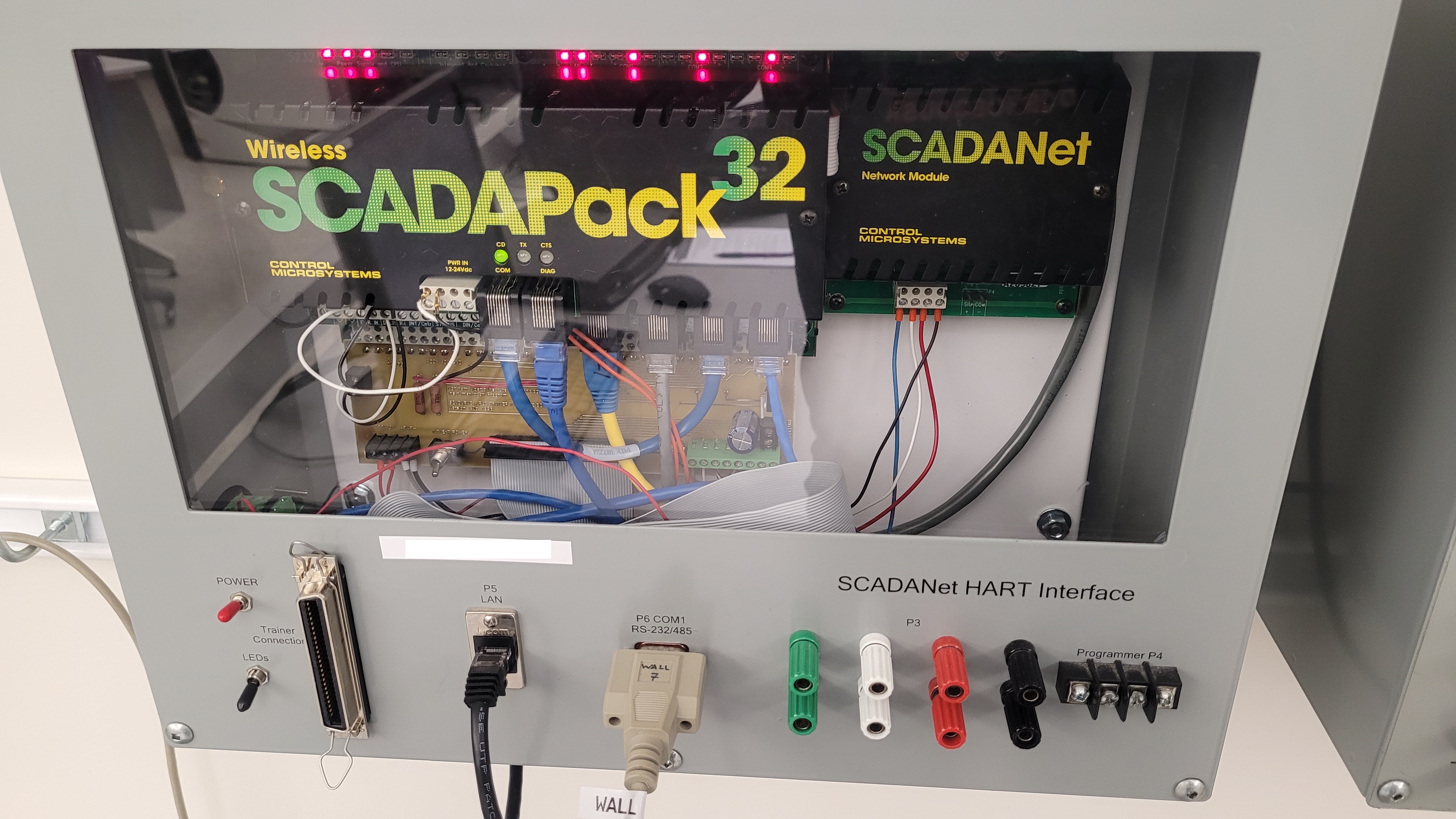
We touched on Schneider's SCADAPack 32 remote terminal unit (RTU) and the development software 'Workbench'. We didn't explore much from it as it was much slower to program with than compared to the AB's PLCs. It did have the ability to program in the different IEC languages.
References
My credentials - PLC Ladder Logic Programming: https://learner.mycreds.ca/r/badges/public/assertion/Ah438rwyQ1KCgOqEc_TvhA
My credentials - PLC Advanced Programming: https://learner.mycreds.ca/r/badges/public/assertion/g2EbFvyxTTmRWccQ12INSw
NAIT course: https://www.nait.ca/coned/programmable-logic-controller