Testing OpenPLC Runtime on Raspberry Pi with Various Slave Devices
TAGS: electronics; automation; industrial; PLC; OpenPLC; Raspberry Pi; Arduino; ESP; Modbus
Why I Did This
In my pursuit to experience industrial automation and PLC programming, I wanted to test the
OpenPLC runtime on my Raspberry Pi.
I wanted to see how effective this runtime was and
how effective the ability to connect to slave devices was. OpenPLC allows users to install
the runtime (the PLC cycle) on a Raspberry Pi, but also can program Arduinos and ESP
microcontrollers to act as I/O extensions (giving the ability to connect more sensors
actuators, but also wireless connectivity), all apparently with the help of Modbus
communication.
Description
Parts: raspberry pi; esp8266; arduino uno;
- Here I tested the open source OpenPLC runtime (a free PLC system to install on your
Raspberry Pi) to see how well it performs on my Pi.
- The runtime can use your Pi's GPIOs to control a multitude of digital and analog devices.
- The runtime receives IEC programs (like Ladder Logic or Function Block Diagrams) from a
free Editor program (by the same people).
- The runtime can extend its GPIOs to include additional devices (slaves) from other cheap
microcontrollers like ESPs and Arduinos.
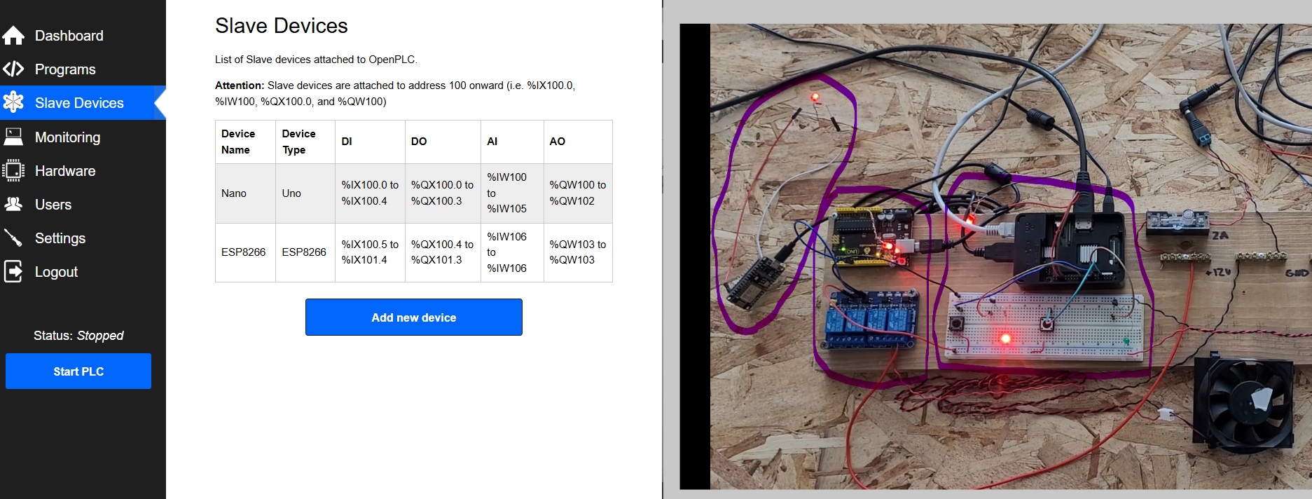
A user can combine multiple microcontrollers to link with a raspberry pi so that you have a large scale (and possibly wireless) I/O system. The runtime webpage interface (Left) allows you to add those slave deivces which take on specific modbus addresses correlating to the to the device's digital and analogs I/Os (starting from addressing 100).
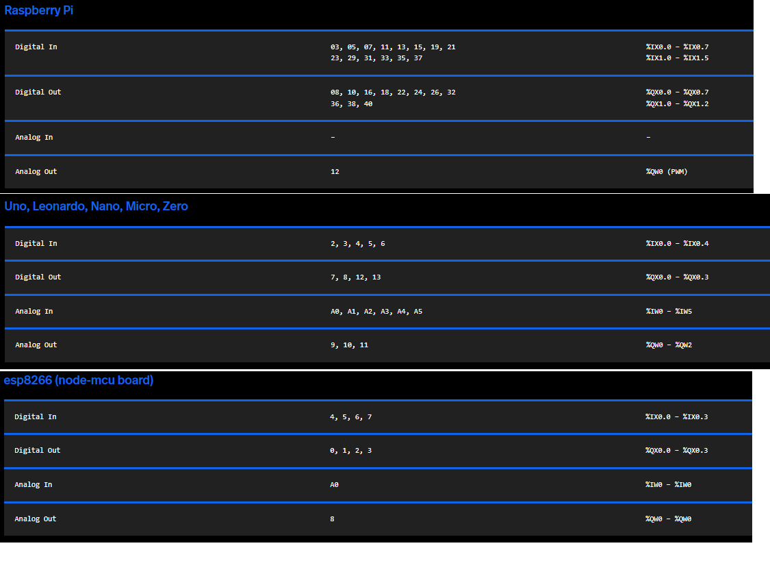
The device's digital and analogs I/Os translate to the physical pin locations (so pin2 might be address %IX100.0).
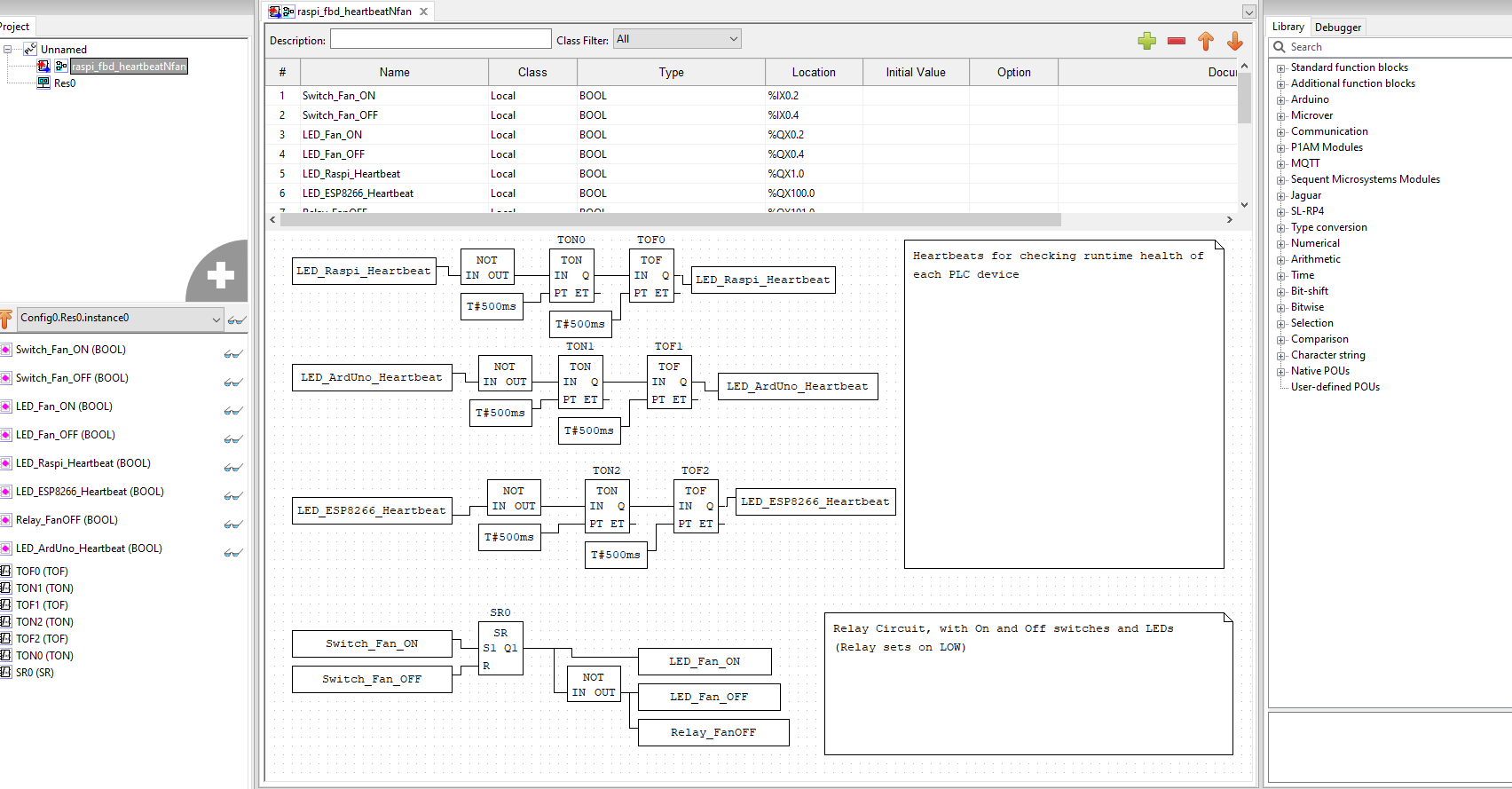
These I/O addresses are used in the editor to signify variables to represent the I/Os and the logic. In this test, the slaves devices are upload with a "Blank" slave program; while the main raspberry pi is uploaded with this function block diagram of heartbeat logic (blinking to show the program is running and not stuck) and a set of on/off switches to control some leds and a fan.
Here in this video I'm demoing the raspberry pi controlling the buttons and LEDs, while a serial slave device (Arduino Uno) controls a relay block for the 12V fan. Both the raspberry pi and uno have red LEDs doing a blinking/heartbeat signal. Additionally, I have a wireless ESP8266 microcontroller actively recieving a heartbeat signal (blinking red LED) from the raspberry pi; the Uno and ESP8266 works solely from slave command of the raspberry pi runtime, as you will see in the next video, when I disable the pi, it disables the Uno's and ESP8266's command.
Here I unplug the raspberry pi, disabling the runtime, which then disables the Uno's and ESP8266's blinking command (the Uno is less apparent because it also receives power from the PI, but the ESP8266 is on separate power and only recieves commands from the Pi).
References
OpenPLC Editor: https://autonomylogic.com/docs/3-1-openplc-editor-overview/
OpenPLC Runtime: https://autonomylogic.com/docs/2-1-openplc-runtime-overview/
OpenPLC Slave Device setup: https://autonomylogic.com/docs/2-6-slave-devices/
OpenPLC Addressing: https://autonomylogic.com/docs/2-4-physical-addressing/